To build an IoT project using Arduino to measure ambient light levels and display the result on an I2C LCD screen in percentage, you can follow these steps:
Components Required:
- Arduino Uno (or any other compatible board)
- LDR (Light Dependent Resistor) or Photoresistor
- 10k Ohm Resistor (for LDR voltage divider circuit)
- I2C LCD Display (1602 LCD or any other compatible I2C screen)
- Jumper wires
- Breadboard
- Optional: Wi-Fi module like ESP8266 or ESP32 (for IoT connectivity, if you want to send data to a cloud or web server)
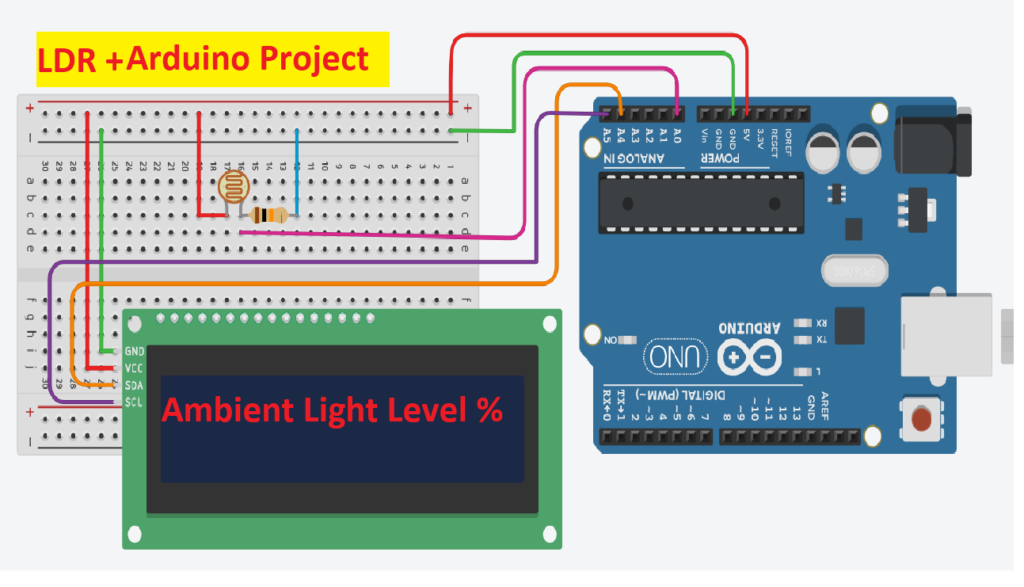
Wiring:
- LDR and Voltage Divider:
- Connect one leg of the LDR to 5V on the Arduino.
- Connect the other leg of the LDR to the A0 pin (analog input) on the Arduino.
- Connect a 10k ohm resistor between the LDR and GND (ground) to form a voltage divider. This allows the Arduino to measure the varying voltage based on light intensity.
- I2C LCD:
- Connect VCC of the I2C LCD to 5V.
- Connect GND to Ground.
- Connect SDA (Data Line) to A4 pin on Arduino (for Arduino Uno).
- Connect SCL (Clock Line) to A5 pin on Arduino (for Arduino Uno).
Arduino Code:
Here’s the step-by-step code to read the ambient light level, convert it to a percentage, and display it on the I2C LCD.
#include <Wire.h>
#include <LiquidCrystal_I2C.h>

// Create an LCD object with I2C address 0x27, and 16 columns and 2 rows
LiquidCrystal_I2C lcd(0x27, 16, 2); // Update this with your I2C address if necessary

// Pin connected to the LDR
const int ldrPin = A0;

void setup() {
  // Initialize serial communication for debugging
  Serial.begin(9600);

  // Initialize the LCD using the correct function
  lcd.init();       // Use 'init()' instead of 'begin()'
  lcd.backlight();  // Turn on the backlight

  // Display initial message
  lcd.setCursor(0, 0);
  lcd.print("Ambient Light:");

  delay(1000);
}

void loop() {
  // Read the value from the LDR
  int ldrValue = analogRead(ldrPin);

  // Map the LDR value (0 to 1023) to a percentage (0 to 100)
  int lightPercentage = map(ldrValue, 0, 1023, 0, 100);

  // Clear the LCD and display the percentage
  lcd.setCursor(0, 1);  // Move to the second row
  lcd.print("Light: ");
  lcd.print(lightPercentage);
  lcd.print("%");

  // Print the value for debugging
  Serial.print("LDR Value: ");
  Serial.print(ldrValue);
  Serial.print(" | Light Percentage: ");
  Serial.println(lightPercentage);

  delay(1000); // Update every 1 second
}
Explanation of the Code:
- Libraries: The
Wirelibrary is for I2C communication, and theLiquidCrystal_I2Clibrary is used to control the I2C LCD. - LCD Initialization: We create an LCD object with the I2C address
0x27(this is a common address, but your module may use a different address). The LCD is initialized with 16 columns and 2 rows. - Reading LDR: The LDR is connected to an analog pin (A0). We use the
analogRead()function to get a value between 0 and 1023, where 0 represents darkness and 1023 represents full brightness. - Mapping: We use the
map()function to convert the analog value (from 0 to 1023) into a percentage (from 0 to 100). This value is then displayed on the LCD. - Display Update: Every second (
delay(1000)), the LCD screen is updated to show the current ambient light level in percentage.
Conclusion:
This simple project helps you measure ambient light levels and display them on an LCD.